Temperature sensor tutorial
Introduction
In this tutorial we will learn how to put together a simple temperature sensor (i.e. a thermometer) with the NodeMCU WIFI module that broadcasts the temperature to the Open Energy-server. You can choose to have one or two sensors connected to the module. Having two sensors makes it possible to measure both indoor and outdoor temperature simultaneously. You will then be able to see both historic data in Grafana and real-time values through our widget.
The parts you will need for this tutorial are:
- A NodeMCU module
- A Micro USB-cable
- A temperature sensor
- A small box which the NodeMCU fits in
- (For installation, not provided at workshop) A Micro USB-cable with adapter (or a battery)
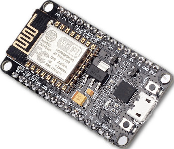
The temperature sensor has three cables. The red one goes to the 3V pin, the black one to ground (GND) and the yellow to the D5 pin in order to fit with the pre-written code. Connect the cables to the NodeMCU as shown below. Also, connect the Micro-USB cable to the NodeMCU.
If you haven’t flashed the NodeMCU yet, go here for instructions on how to do so.
Great, now we're ready to start setting it up. The following steps are installing the development tools for the virtual machine, downloading the code from GitHub and uploading the code to the NodeMCU.
1. Install development tools
a) Download or copy all the files that are in the workshop bundle online (Beware that it is 3.22 GB and takes a while to download) or from the USB sticks that will be available during the physical workshop to your computer.
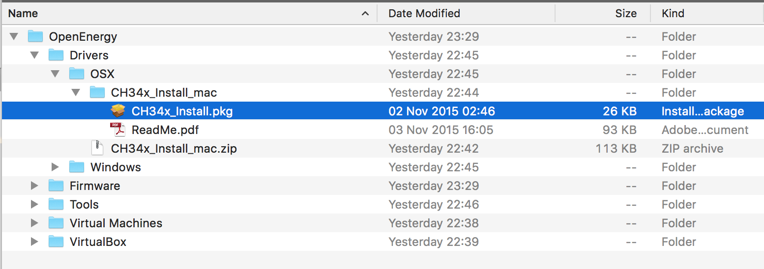
b) Open the Driver folder and install the driver matching your operating system.
c) Open the folder named VirtualBox run the installation file that matches your operating system. Depending on what NodeMCU module you have there are two options in terms of drivers (see table below).
|
|
|
|---|---|---|
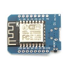
| Version 2 (CP2102) | Version 3 (CH34x) | D1 mini (CH34x) |
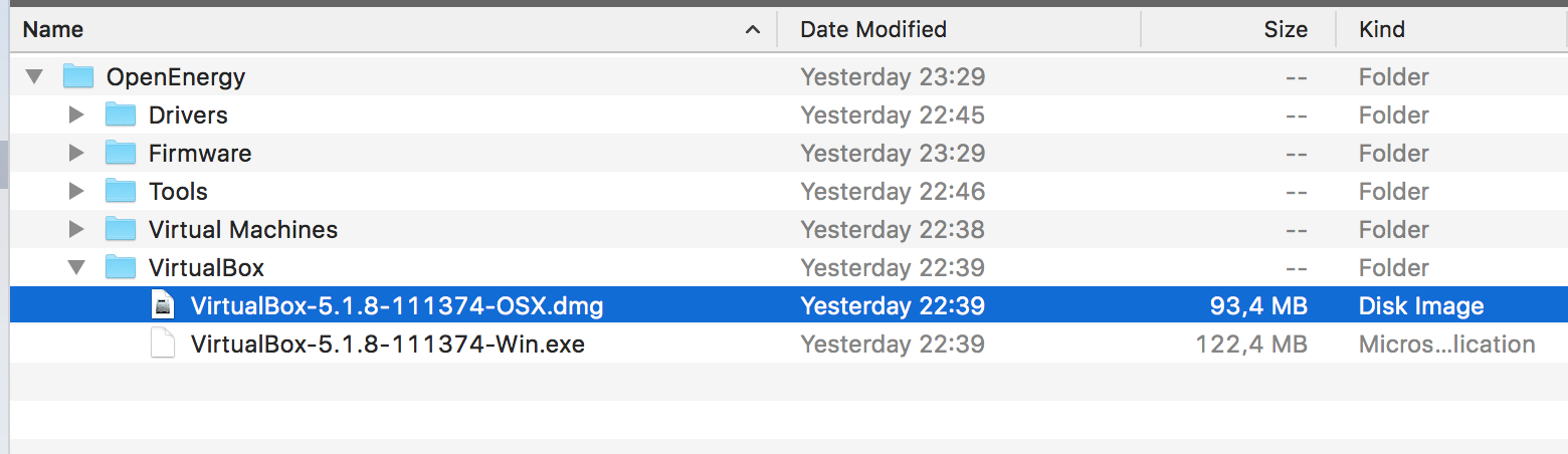
d) Open the folder named "Virtual machines" and click on the file named OpenEnergyToolbox.zip to unzip the the virtual machine (this can take some time).
e) Open the folder that was created named OpenEnergyToolbox and double click on the OpenEnergyToolbox.vbox file. A virtual machine will now start with all the development tools preinstalled.
f) Connect your NodeMCU with a USB cable to your computer if you haven't done so already.
2. Downloading the code from GitHub
Good, now we have the software ready. Now we need to download the conveniently pre-written code before we can upload it to the NodeMCU. However, just downloading the code files in your ordinary web browser won't work, we need to do this in the virtual machine we just started.
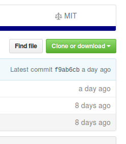
a) Inside the virtual machine, open up Firefox and go to github.com/op-en . There you will see a project called NODEMCU-TempSensor.
b) Open the project and click the "Clone or Download” button to the right and download the files as a zip.
c) Click on the Files icon on the taskbar (to the left) and go into Downloads, unzip the NodeMCU-TempSensor-master.zip file by double-clicking and then Extract.
Good, we now have the code for the NodeMCU downloaded. Now we just need to write the files to the module with a little help from ESPlorer.
In the virtual machine, go to the navigation bar in the top menu, then click Device -> USB and select QinSengElectronics USB2.0-Serial or Silicon Labs CP2102 USB to UART Bridge Controller (the name might vary on different operating systems). The name should appear after you plugged in the NodeMCU and disappear when you remove it.
3. Upload the program
a) Open the ESPlorer program. It can be found in a folder on the desktop called ESPlorer and is started by double clicking the ESPlorer.jar file. Wait until it starts.
b) Check that settings in the top right area are as in the picture and click the Open button on the right side of the program.
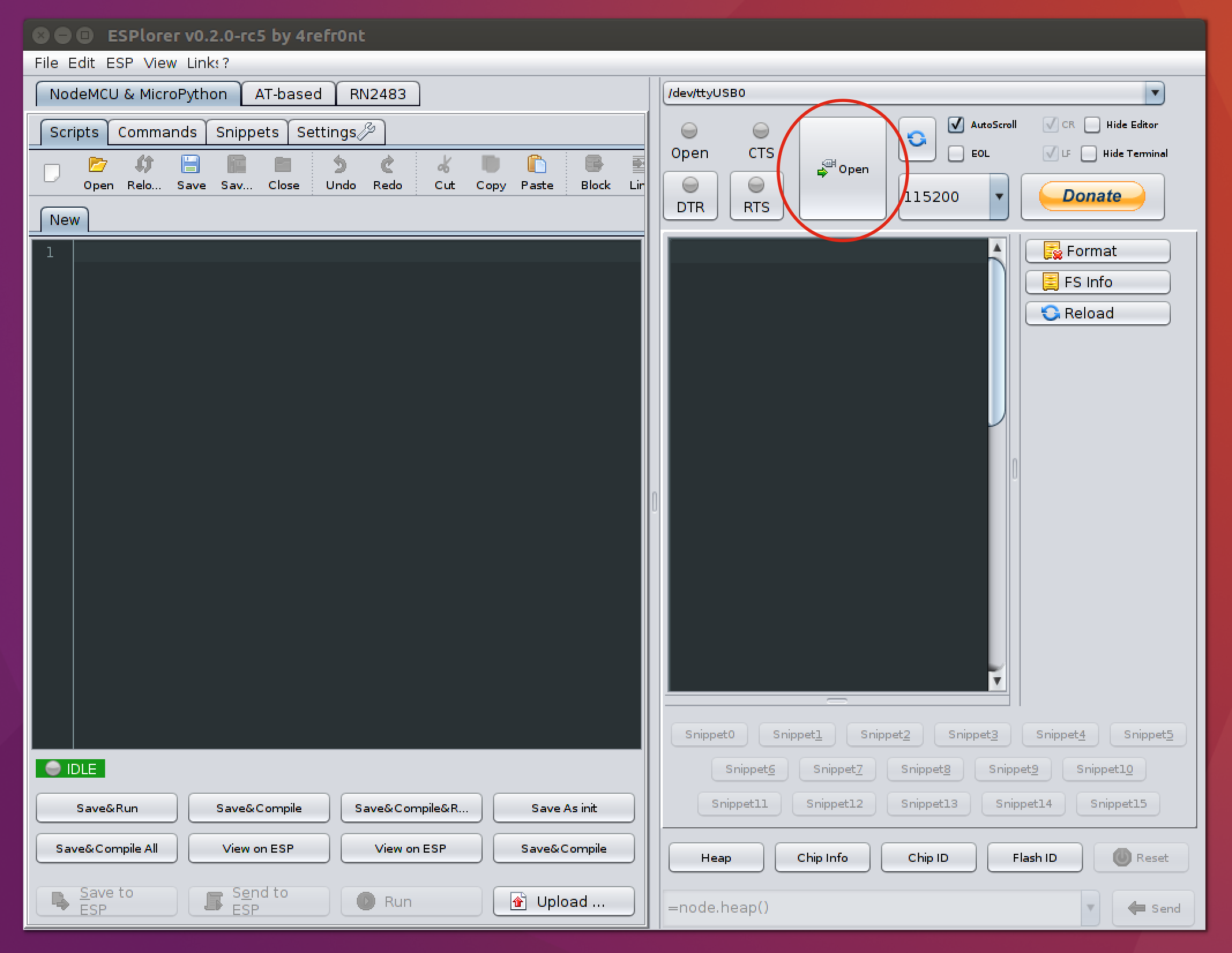
c) To check if you are connected to the NodeMCU you can now either click the Heap button in the bottom towards the middle or press the reset button on the NodeMCU module itself and you should get some printouts in the terminal.
You can also test that you have a good connection to the module by entering
print("Hello world")
in the white box on the bottom right and then press the send button text to it. The readout should say
print("Hello world!")
Hello world!
If you don't get the above reply you need to start trouble shouting your connection to the NodeMCU.
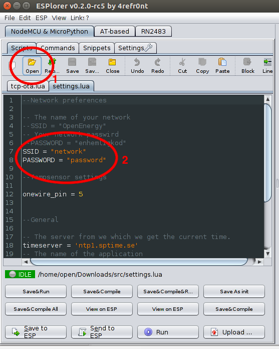
d) Now click Open (to the far left) and navigate to Downloads where you will find the code files. Open the file settings.lua inside the src folder. This file contains WIFI credentials that you will need to change when deploying the monitor in your home. Change the SSID and password in the settings.lua file.
Click the button Save to ESP in the left bottom corner to send the file to the NodeMCU.
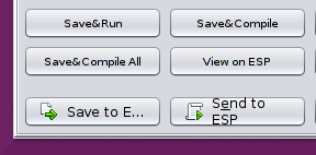
Now open all other files inside the src folder and save them to the NodeMCU with the same button. Take care to save the init.lua file last.
After you are done you can press the reload button on the far right side (blue arrows) and it should look like this:
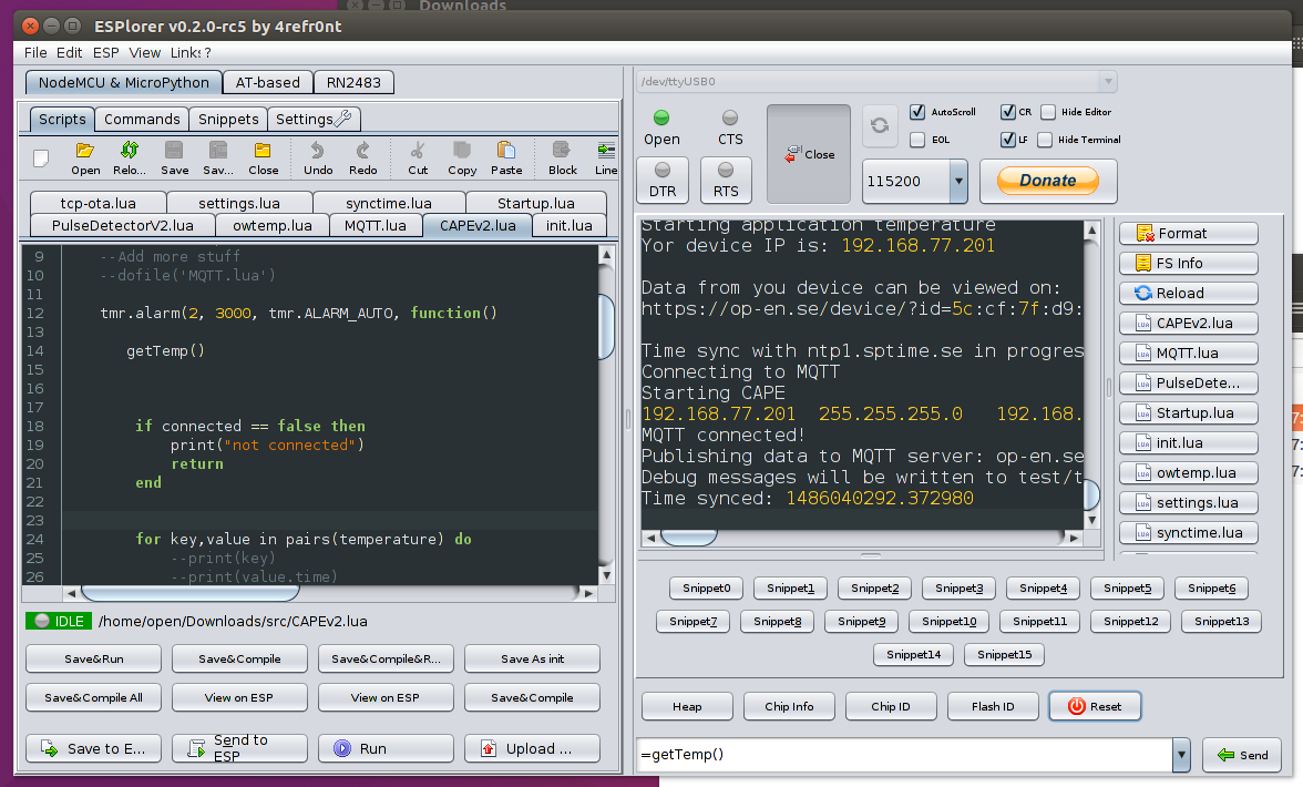
The list of files on the right are the files currently on the NodeMCU.
Now we have all the files needed on the NodeMCU, it should also deliver some printouts as below whenever it senses a change in temperature and uploads it to the server.

4. Visualizing the data online
To see the temperature in real-time, you can either choose to see the graph for a historic overview or a real-time widget.
For both strategies you will need the ID of the NodeMCU (it is printed in the terminal for every sending, and has the format: XX:XX:XX:XX:XX for the MCU followed by a code for the temperature sensor like 28FF525680160594
4.1 Graphana version
Go to https://op-en.se/graphs . In the dropdown Home menu, scroll down and choose Temperature sensors. The default two sensors showing are placed in Electrum building, Kista. In the top field labeled sensor:, choose the ID corresponding to your NodeMCU.
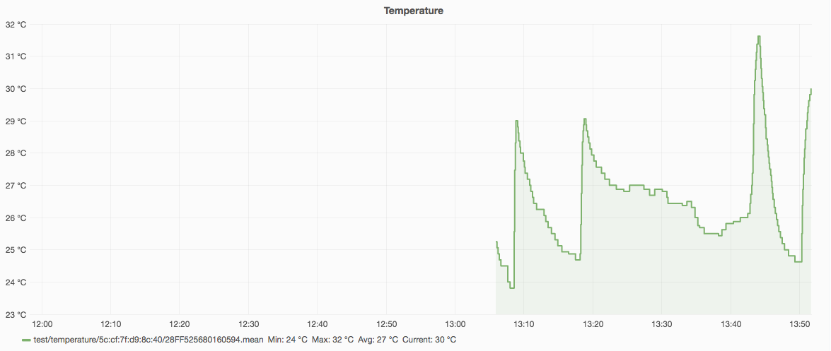
If you start zooming in the graph you will get something looking like below. If you click on the Time in the upper menu, you can choose the refreshing interval.
4.2 Widget version
If you go to https://op-en.se/visualizing/#html5 you can see some widgets already available, among others the temperature widget. If you have done the energy meter tutorial previously, you remember that by entering your NodeMCU ID in the link, you could see the amount of electricity being used in real time.
In the same way, you can go to:
https://op-en.se/assets/widgets/widget-termometer.html?topic=test/temperature/5c:cf:7f:d9:8c:40/28FF525680160594&decimals=1&subproperty=temperature
but edit the ID for the MCU (5c:cf:7f:d9:8c:40) and the temperature sensor (/28FF525680160594) to your corresponding IDs.

Cool! Now all that is left to do is put the NodeMCU into the small box, make two small holes for the cables and find a power source (outlet or battery) for your temperature sensor where it should be placed. Remember that for accurate measuring, the sensor indoors should be placed at least 1 m from the window and 1 m from the floor.
5. How to make a QR-code (optional)
If you want, you can make an individual QR-code which directs to your thermometer. Copy the link containing your id for NodeMCU and the sensor. Go to http://goqr.me and paste the link into the text field. Click Download, and choose PNG. You can then print the QR-code and attach it onto the plastic box containing the NodeMCU.